Search

Fawn's Blog

The making of digital and physical things

Electronic Clay Jewelry Kit

Overview

According to the Labor Department’s Workplace projections for 2018, nine of the 10 fastest-growing occupations that require at least a bachelor’s degree will require significant scientific or mathematical training. Some of the largest increases will be in engineering- and computer-related fields in which women currently only hold one-quarter or fewer of the jobs. Gender differences in self-confidence in STEM subjects start in middle school and increase thereafter. Thus the years from middle school to high school are the prime time to initiate interest for females in the STEM subjects. Researches also show that cultural factors, rather than a lack of aptitude or intrinsic interest make subjects such as computer science or engineering less appealing to young women. For my final project, I hope to create a craft kit that will engages young women in computing/engineering projects that are more relevant to them. It will serve as a non-intimidating channel for young women to gain hands-on experience while building something beautiful, expressive, and useful that they can share with their family and friends.

Process

I first researched on current kits on the market. There is a clear gap in technology-based craft kits for young women.

Since clay is easily manipulated and familiar to the target audience. Clay would be a great material for a craft kit.

I designed four mini projects for this kit:

I have documented the steps in how to make three projects. I envision this would be the way the instructions will look in a real craft kit.

Thermochromic Brooch

Picture of the final product

List of materials needed

Step-by Step Instructions

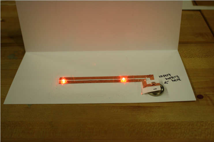
A pre-circuited base would come with each kit, this would allow the user to create interesting projects without having equipments such as a solder.

Demo

Thermochromic Brooch 2

Picture of the final product

List of materials needed

Step-by-Step Instructions

Demo

Pressure sensor necklace

Picture of the final product

Step-by-Step Instructions

Comparison of modeling materials used

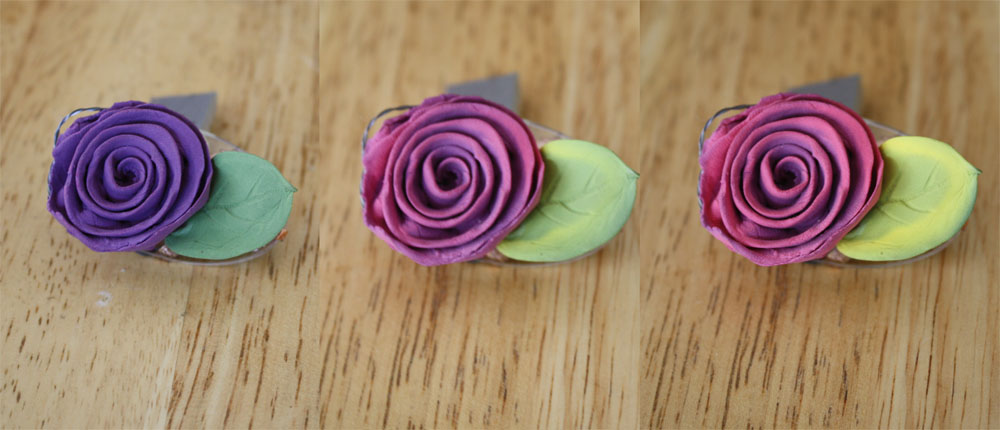
Note that the thermochromic clay is made by mixing thermochromic powder and regular clay. Both types of clay mixed easily and well with the thermochromic powder. It’s an activity that children can undertake on their own.

Comparison of conductive materials used

The main conductive materials used are:

Conductive thread: conductive thread worked best in both creating jewelry and creating heat in the thermochromic clay. It used the less power compared with conductive fabric. It created more heat compared to copper tape. Conductive ink on paper was also considered by painting on a piece of paper and inserting the paper into the clay. The procedure was difficult and was abandoned. In the future, I plan to also experimenting with painting on dried clay. However, since conductive silver ink is expensive, it may not be the best option for the kit.

Conductive clay: conductive clay was used in the brooch project. It was created by mixing carbon powder with clay. The clay was fairly conductive when dried, It heated up and cooled the crystal thermochromic ink very quickly. This is an area I want to explore more and create more projects. Some downsides are that the clay is black in color, thus may not be appealing when not used with crystal ink. The clay is also brittle and cracks easily. More experimentation with percentage of carbon powder and clay needs to be documented to derive the best combination.

Conclusion

The concept of my final project is a technology-based activity kits that user can purchase and be able to create all the projects on their own. Through learning about computing and engineering in an informal and hands-on manner, this craft kit could contribute towards bridging the gender gap in STEM studies. More experimentation and more relevant lessons need to be developed to help achieve the craft kit’s mission. You can also download the PDF version of the post here.

Featured post

Flappy Bird in a Box Hack (In Real Life Version)

Flappy Bird IRL version made with Arduino, two servo motors, reed switch, and magnets. Inspired by the Mario in a Box game.

Furry Elephant

Image

Furry Elephant is an introductory-level robot project that aims to introduce robotics to people in a more familiar and appealing way. The robot interacts with various objects and people to reflect its characteristics and personalities. I designed the project with the below considerations in mind:

  • Affordability – Made from everyday materials
  • Interactivity – Interact with people and other objects
  • Attractive –  Cute and furry design
  • Technology – Use simple technology to demonstrate difficult electronic concepts

Elephant in action:

This project was inspired by the Robobrrd project.

Koinobori

Koinobori means “koi rising” in Japanese. Koinobori is a koi-shaped wind socks traditionally flown in Japan to celebrate Tango no Sekku. From April to early May, many landscapes across Japan are decorated with koinobori. I wanted to recreate this traditional craft with a new computational twist.

I created a koi design using a Voronoi diagram in Processing and Adobe Illustrator:

Here’s the embroidery machine creating the stitches and the finished product:

I then sewed the fabric in a tube shape and also sewed on a top and bottom to create a more finished look.

I wanted the steamer to light up as the koinobori gets  blown back and forth. It would be a great representation of the koinobori during the night time. Here’s the circuitry:

Here’s the final finished product, as the koinobori sways in the wind, it will light up:

Simple Light-up Card

A happy birthday card to my dear sister! 😀

ImageHere is the finished product

ImageThe inside of the card is a parallel circuit consisting of two LEDs, copper tape as the conductor, and a battery.Image

Image

Image

Ta-da!

Wiggling Bunny

Easter is right around the corner! Wiggling Bunny is project that will bring a paper bunny to life as it wiggles and moves its ears. I originally got the idea when I was om nom nom on some mochi at Minamoto Kitchoan in SF. I saw this really cute rabbit paper box, but it costed $6! For paper? I say “Nay”.

I then thought about how I could construct a similar box from paper. After a few trials, I’ve created this template. Here is the finished product, not bad, eh?


In order to achieve the wiggle effect of the ears, I planned to use shape changing memory alloy, which shrinks in length when it’s heated to certain temperature. The temperature can be raised through passing an electrical current through the circuitry that will be formed on the bunny’s ear. You can watch a video of shape changing memory alloy in action here.

Steps to create this project:

1. Cut out the bunny shaped template pictured below. You can download the pattern here.

2. Use conductive tape, Flexinol (types of shape changing memory alloy), and mosfet to form the circuitry depicted below. Use thread to secure the flexible around the ears area. Also put snaps on the paper to make space for the Lillypad Arduino micro-controller.

Note: make sure the Flexinol is sown snugly on the ears

Note: make sure all the connection point on of the copper tape are secure, use a multimeter to check conductivity.

This is how the front of the bunny looks. make sure all connection points are secure.

3. Program the Arduino board and snap on the bunny, assemble the bunny in shape

When I tested this project, it did not work. I think it’s because I did not sew the Flexinol on the ears tight enough, thus even though it shrunk, it did not cause a movement. I will recreate the project using another construction of how the Flexinol adheres to the eras. TBD…

Update

I changed the construction of how I attached the Flexinol to the ears. I used two pins to secure the Flexinol.

…and it WORKS!

Draw-bot

Last weekend, I had the opportunity to work with the students at the South End Technology Center  on a new weekly program called Artbotics where students engage in creative projects at the intersection of robotics and art. We started the day with many programming related activities that we designed, but the one the students seem to enjoy the most was the “Drawing Robot” activity.

Students used Modkit to program their own robot cars that will draw various patterns as coded by the students. The robot car was assembled using Lego pieces, cardboard, Arduino board, and a battery attachment. The students quickly learned how to program their cars and experimented with commands in order to get the right angle and line length they wanted for their drawings.

Testing out the code:


Although for many students, the drawings weren’t exactly perfect the first time, they were eager to go back and adjust the code in order to get the exact look that they wanted. I think the students really enjoyed the iterations of adjusting and testing. Many of them were very surprised to see how the code translated to certain patterns. This reminded me of how I shared similar feeling when I was working on my computational design assignment that same week.

One of the final products

Dino-light

I was talking to a 6-8th grade robotics teacher during a workshop few weeks ago, she was telling me about how they are using Lego Mindstorm to learn about programming and robotics. She mentioned that the girls often complained how the robots were “ugly” and wanted to decorate it. She also told me how one girl was cradling and petting the robot while programming it. I wanted to create an example robot project where the “robot” was cute and can be easily decorated. I’ve made a simple prototype of a dinosaur that has a pressure sensor on it’s hand. The dinosaur will light up when you hold its hand.

Watch Dino in action

1.  Here is the original sketch

2. I first laser-cut 6 pieces of wood to make Dino’s body. I posted a revised template here.

3. Then I glued all the parts together, though press-fitting would’ve been much better.

4. Then I made the “skin” of Dino out of felt

5. I sewed the LEDs onto the felt in two intersecting parallel circuits, I used tape to make sure the circuits did not short each other. I used Scotch tape, again, I think masking tape would’ve worked better.

6. “Look at my beautiful skin” – Dino

7. Then I made the arm using tape, velostat, and conductive thread and covered the arm with felt.

8. Finally, adhere the skin and the arm to the body. I used Scotch tape again here because I wanted to be able to take it apart when I add other mechanisms to Dino in the future.

9. The finished Dino

Dino enjoying a cup of coffee…


Leaves of Brass

I wanted to experiment with a natural material that can be found everywhere.I decided to use a leaf because it had a beautiful surface with vines that resembled electrical circuits. I experimented with how various conductive materials behaved on a leaf and finally formed an electric circuit on the surface of the leaf.

Conductive Ink

Conductive ink was drawn on a piece of leaf to create an electrical circuit using a wooden stick dipped in silver ink. Brush made it difficult to control precision; pen often scratched the surface of the leaf and did not provide enough ink flow. Compared with other conductive material, the conductive ink adhered to the surface of the leaf the best, but did not connect to the microcontroller and battery very well. Silver ink painted using a stick was the most effective.

Copper-plating

Each circuit was then copper-plated separately. Time spent in copper bath directly determined the color of copper plates. For example, 3 minutes in bath yielded a dull copper color while 10 minutes in bath resulted in a bright copper color. Plating surface also determines level of adhesiveness of the copper. For example, the copper on the stem adhered well to the surface; however the copper on the leaf was fragile and broke off easily when the leaf was scrunched. The copper circuit that fell off was glued back. Electrometer also showed that silver ink was more conductive than copper. The resistance of silver ink was 0.0-0.1 Ohm and the resistivity of copper was 0.2-0.3 Ohm.

Conductive thread

Conductive string could be a substitute of ink and copper. However it broke the leaf easily. The surface of the leaf was too fragile. The metal-coated string was rougher and broke the leaf easier. This method was not pursued in the final product.

Connecting the circuits

Microcontroller and battery were connected to the circuit through soldering and conductive ink. Soldering provided a stronger bond than conductive ink and glue especially due to the slippery surface of the leaf.

The circuit will be completed when the user touches the input (the stem) while holding on to ground. Both are copper-plated for easy identification. The LEDs turn on and off when the input is touched.

Demo

Challenges

Overall, fresh leaves were a difficult surface to work on due to its fragility and slippery surface. This could possibly be solved if the leaf was dry. Soldering provided better connection than ink alone.

Potential application

This could be used in an interactive installation where synthetic fabric leaves are attached to a real tree and people can touch individual leaves (inputs) and lights will turn on and off depending which input the user touches.

Download a copy of the presentation here.

Blog at WordPress.com.

Up ↑